

How to Use the 360° View Monitor
Displaying images of the vehicle front/sides
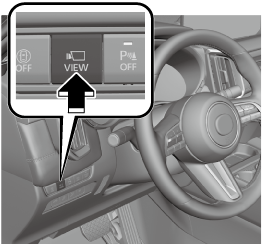
Images are displayed on the center display.
-
When the selector lever is in the R position, images of the front/sides of the vehicle are not displayed.
-
If any of the following conditions are met, image display of the front/sides of the vehicle ends.
-
Switches around the commander knob are pressed.
-
The vehicle is driven at less than 15 km/h (9.3 mph) for about 4 minutes and 30 seconds.
-
The vehicle speed is 15 km/h (9.3 mph) or faster.
-
The vehicle is driven at 15 km/h (9.3 mph) or faster for 8 seconds.
-
The selector lever is shifted to the P position.
-


Displaying images of the vehicle rear
Shift the selector lever to the R position.
Images are displayed on the center display.
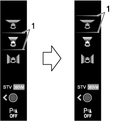
Switching the image
-
Turn the commander knob and move the cursor to the desired image.
-
Cursor
-
-
Press the commander knob to select the image to display.
Move the commander knob sideways to switch between 360° View mode (360VM) and See-Through View mode (STV).
Viewing the screen
-
Because there might be a difference between the image displayed on the screen and the actual conditions, always check the safety of the surrounding area directly with your eyes when driving.
-
Images may be difficult to see due to the weather and surrounding environment, however this does not indicate a problem.
-
The rear view, rear wide view, and rear See-Through View images are reversed left and right
-
The actual tires may appear in the top view and front See-Through View.
-
Obstructions displayed in views other than the top view may not be displayed on the top view.
-
The areas in black on the top view, front See-Through View, and rear See-Through View and the seams where each of camera images merge are blind spots.
-
The top view, front See-Through View, and rear See-Through View are displayed by processing the images taken by each camera. Therefore, images may be displayed as follows.
-
Color or brightness displayed on the screen may appear differently than in actuality.
-
If the vehicle tilts, the image may appear distorted.
-
Lines on the road may appear distorted at the seams where each of the camera images merge.
-
-
Screen brightness and contrast can be adjusted.
Set using “Settings” on the Mazda Connect home screen or consult an Authorized Mazda Dealer.
-
The parking sensor detection range has limitations. For details, refer to the parking sensor entry.
Refer to Parking Sensor (Search).
-
The screen display may differ from the actual display.
Top view, front view
|
Indication |
Content |
|
|---|---|---|
|
1 |
Tire icon |
Indicates the tire direction. Moves in conjunction with the steering wheel operation. |
|
2 |
Projected vehicle path lines (red/yellow) |
Indicates the approximate projected path of the vehicle. Moves in conjunction with the steering wheel operation. a) Indicates the path where the edge of the front bumper is expected to travel. b) Indicates the path where the inner side of the vehicle is expected to travel. |
|
3 |
Parking sensor detection indication |
Indicates the obstruction detection status. |
|
4 |
Vehicle width guide lines (blue) |
Indicates the approximate width of the vehicle. |
|
5 |
Projected vehicle path distance guide lines (red/yellow) |
Indicates the distance (from front end of bumper) in front of the vehicle.
|
|
6 |
View status icon |
Indicates which image is selected. |
|
7 |
Mode switching icon |
Indicates which mode is selected. |
|
8 |
Parking sensor status icon |
Indicates that the parking sensor has a problem or it is switched off. |
Top view, front wide view
|
Indication |
Content |
|
|---|---|---|
|
1 |
Tire icon |
Indicates the tire direction. Moves in conjunction with the steering wheel operation. |
|
2 |
Projected vehicle path lines (red/yellow) |
Indicates the approximate projected path of the vehicle. Moves in conjunction with the steering wheel operation. a) Indicates the path where the edge of the front bumper is expected to travel. b) Indicates the path where the inner side of the vehicle is expected to travel. |
|
3 |
Parking sensor detection indication |
Indicates the obstruction detection status. |
|
4 |
Extended vehicle width lines and distance guide lines (red/blue) |
Indicates the approximate width of the vehicle and the distance (from front end of bumper) in front of the vehicle.
|
|
5 |
View status icon |
Indicates which image is selected. |
|
6 |
Mode switching icon |
Indicates which mode is selected. |
|
7 |
Parking sensor status icon |
Indicates that the parking sensor has a problem or it is switched off. |
The front wide view displays the image in front of the vehicle at a wide angle and corrects the image to help detect approaching obstructions from the side. Therefore, it differs from the actual view.
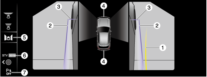
Side view
|
Indication |
Content |
|
|---|---|---|
|
1 |
Projected vehicle path lines (yellow) |
Indicates the approximate projected path of the vehicle. Moves in conjunction with the steering wheel operation. The projected vehicle path lines (yellow) indicate the path the inner side of the vehicle is expected to travel. |
|
2 |
Vehicle parallel guide lines (blue) |
Indicates the approximate vehicle width including the outside mirrors. |
|
3 |
Vehicle front end guide lines (blue) |
Indicates the front edge of the vehicle (front edge of the bumper). |
|
4 |
Parking sensor detection indication |
Indicates the obstruction detection status. |
|
5 |
View status icon |
Indicates which image is selected. |
|
6 |
Mode switching icon |
Indicates which mode is selected. |
|
7 |
Parking sensor status icon |
Indicates that the parking sensor has a problem or it is switched off. |
Do not turn the steering wheel any more until the vehicle has passed the obstruction, even if the obstruction is not visible on the side view image. If the steering wheel is turned even more, the vehicle may contact the obstruction if it is turned sharply.
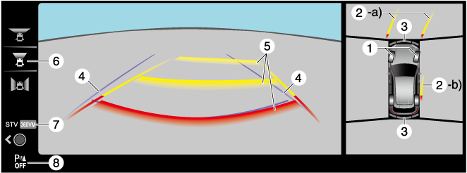
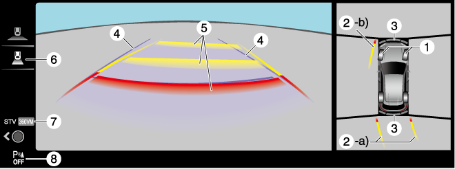
Top view, rear view
|
Indication |
Content |
|
|---|---|---|
|
1 |
Tire icon |
Indicates the tire direction. Moves in conjunction with the steering wheel operation. |
|
2 |
Projected vehicle path lines (red/yellow) |
Indicates the approximate projected path of the vehicle. Moves in conjunction with the steering wheel operation. a) Indicates the path where the rear end of the rear bumper passes as a reference. b) Indicates the path where the outer side of the vehicle is expected to travel. |
|
3 |
Parking sensor detection indication |
Indicates the obstruction detection status. |
|
4 |
Vehicle width guide lines (blue) |
Indicates the approximate width of the vehicle. |
|
5 |
Projected vehicle path distance guide lines (red/yellow) |
These guide lines indicate the approximate distance to a point measured from the rear of the vehicle (from the end of the bumper).
|
|
6 |
View status icon |
Indicates which image is selected. |
|
7 |
Mode switching icon |
Indicates which mode is selected. |
|
8 |
Parking sensor status icon |
Indicates that the parking sensor has a problem or it is switched off. |
The front of the vehicle swings out wide when turning the steering wheel while reversing. Maintain sufficient distance between the vehicle and an obstruction.
-
Even though the back end of the parking space (or garage) displayed on the screen and distance guide lines appear parallel, they may not actually be parallel.
-
When parking in a space with a division line on only one side of the parking space, even though the division line and the vehicle width guide line appear parallel, they may not actually be parallel.
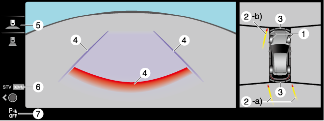
Top view, rear wide view
|
Indication |
Content |
|
|---|---|---|
|
1 |
Tire icon |
Indicates the tire direction. Moves in conjunction with the steering wheel operation. |
|
2 |
Projected vehicle path lines (red/yellow) |
Indicates the approximate projected path of the vehicle. Moves in conjunction with the steering wheel operation. a) Indicates the path where the rear end of the rear bumper passes as a reference. b) Indicates the path where the outer side of the vehicle is expected to travel. |
|
3 |
Parking sensor detection indication |
Indicates the obstruction detection status. |
|
4 |
Extended vehicle width lines and distance guide lines (red/blue) |
These guide lines indicate the approximate width of the vehicle and distance to a point measured from the rear of the vehicle (from the end of the bumper).
|
|
5 |
View status icon |
Indicates which image is selected. |
|
6 |
Mode switching icon |
Indicates which mode is selected. |
|
7 |
Parking sensor status icon |
Indicates that the parking sensor has a problem or it is switched off. |
The rear wide view displays the image at the rear of the vehicle at a wide angle and corrects the image to help detect approaching obstructions from the side. Therefore, it differs from the actual view.
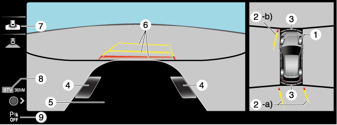
Top view, front See-Through View
|
Indication |
Content |
|
|---|---|---|
|
1 |
Tire icon |
Indicates the tire direction. Moves in conjunction with the steering wheel operation. |
|
2 |
Projected vehicle path lines (red/yellow) |
Indicates the approximate projected path of the vehicle. Moves in conjunction with the steering wheel operation. a) Indicates the path where the edge of the front bumper is expected to travel. b) Indicates the path where the inner side of the vehicle is expected to travel. |
|
3 |
Parking sensor detection indication |
Indicates the obstruction detection status. |
|
4 |
Tire graphic |
Indicates the approximate position of the tires. |
|
5 |
Vehicle bottom graphic |
Indicates the estimated bottom of the vehicle. |
|
6 |
Projected vehicle path distance guide lines (red/yellow) |
Indicates the distance (from front end of bumper) in front of the vehicle.
|
|
7 |
View status icon |
Indicates which image is selected. |
|
8 |
Mode switching icon |
Indicates which mode is selected. |
|
9 |
Parking sensor status icon |
Indicates that the parking sensor has a problem or it is switched off. |
The front See-Through View may be displayed as follows.
-
The ground and three-dimensional objects may appear curved.
-
The representation of three-dimensional objects changes at the joints of images and the same object may appear to be duplicated or not connected.
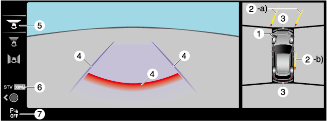
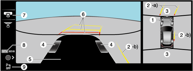
Top view, rear See-Through View
|
Indication |
Content |
|
|---|---|---|
|
1 |
Tire icon |
Indicates the tire direction. Moves in conjunction with the steering wheel operation. |
|
2 |
Projected vehicle path lines (red/yellow) |
Indicates the approximate projected path of the vehicle. Moves in conjunction with the steering wheel operation. a) Indicates the path where the rear end of the rear bumper passes as a reference. b) Indicates the path where the outer side of the vehicle is expected to travel. |
|
3 |
Parking sensor detection indication |
Indicates the obstruction detection status. |
|
4 |
Tire graphic |
Indicates the approximate position of the tires. |
|
5 |
Vehicle bottom graphic |
Indicates the estimated bottom of the vehicle. |
|
6 |
Projected vehicle path distance guide lines (red/yellow) |
These guide lines indicate the approximate distance to a point measured from the rear of the vehicle (from the end of the bumper).
|
|
7 |
View status icon |
Indicates which image is selected. |
|
8 |
Mode switching icon |
Indicates which mode is selected. |
|
9 |
Parking sensor status icon |
Indicates that the parking sensor has a problem or it is switched off. |
The rear See-Through View may be displayed as follows.
-
The ground and three-dimensional objects may appear curved.
-
Expressions such as three-dimensional objects change at the seams of the image, and the same objects may be displayed in duplicate or may be connected and not visible.
System problem indication
In the following cases, there might be a problem with the system. Have the vehicle inspected by an Authorized Mazda Dealer.
-
"No camera signal." is displayed on the center display.
-
The display on the center display does not switch to the camera image even if the selector lever is shifted to the R position.
-
The display on the center display does not switch to the camera image even if the 360° view monitor switch is pressed.
-
A portion of the display on the center display is black.
